Input and Boundaries
On the Input and Boundaries form (Wellbore Stability > Predict Mud Weight > Predict Mud Weight Window > Input and Boundaries), you use all the input defined in the input definition with the aim to calculate the collapse pressure. You calculate the critical mud pressures that correspond to wellbore collapse, initiation of tensile fractures, and fracture link-up. An optimal program of casing setting depths is proposed from this data. You can also manually design casing with easy-to-use graphical tools, and can consider kick tolerances during the casing design by incorporating them into the mud window as an adjustable safety factor. At any depth of interest, you can analyze in detail the required mud weight when the drilling direction or the rock strength changes.
To predict mud weight
-
Use the Input and Boundaries form (Wellbore Stability > Predict Mud Weight> Input and Boundaries) to specify input data needed to calculate the mud window.
-
In the Critical BO width field, select the Critical Break Out Width to use for the calculation.
-
Specify the lower and upper bounds and mud invasion factor (if calculating Link-up pressure) for the calculation.
Lower bound You can define the lower bound as the pore pressure, the borehole collapse pressure, or the maximum of these two. For more information, see Predict Mud Weight View.
Upper bound You may define the upper bound as the minimum stress, fracture gradient, or a number of fracture gradient and maximum stress combinations. For more information, see Predict Mud Weight View.
Mud invasion factor A percentage defining how far the drilling mud penetrates into a tensile fracture. The default value is 98%, but you can enter another value.
Poor fluid penetration makes it more difficult to extend a fracture and prevents fracture propagation until the net pressure (that is, the excess pressure of fluid in the fracture above the least principal stress) increases sufficiently to overcome the stress concentration at the fracture tip. This results from the inability of the fluid to reach this critical region. Oil-based muds are assumed to penetrate to the fracture tip; therefore, a mud invasion value of 100% is recommended to model their behavior. Mud invasion values close to, or even below, the default 98% are appropriate for water-based muds and muds with inhibitors. This factor acts on fracture grow only.
- Specify the casing design in the Mud Window Settings section.
- Click on the Show Well Table button to open the Well Table with the Casings tab active and visualize the schematic data in the table. To edit the casing design, click on the Edit Casing Scheme button to open the Casing Scheme form.
- Click on the Show Well View button to open the Predict Mud Weight view that displays the mud weight log, the lithology track and the well schematic track.
- To Add a new row to the mud window table, click on the Add Casing Section button. By default, the new row is appended to the end of the table with the Casing MD and OD values populated. You can change these values if necessary.
- In the Kick Tolerance Settings, select the Consider static kick tolerance checkbox to take into account the kick volume, density, and intensity parameters. Click on the Show button to open the Static Kick Tolerance table and specify the required parameters.
- Click OK to go to the next form, Along Wellbore.
Casing design Select an existing casing design from the drop-down list or create a new casing design for the active case. To create a new casing design, or copy an existing design, type a casing name into the Casings design entry field and then click Create Copy or Add New Casing Design.
 Create copy of existing case Enter a new casing design name in the Casings design entry field to activate the button. Click on the Create Copy button to create a copy of the existing design and populate the Well schematic track in the Predict Mud Weight view with the copied design.
 Add new casing design Enter a new casing design name in the Casings design entry field to activate the button. Click on the Add New Casing Design button to create a new casing design. For automatic designs, the Casing MD in the table is filled in automatically based on your input data. Enter the required values for the design in the OD column.
When designing the casing, keep in mind that the application builds the casing from the top down. Attempting to build the casing from the bottom up, results in an error message generated when the second MD value is less than the previous value.
 Delete casing design Removes the casing design.
The casing design table on this form is synchronized with the Along Wellbore casing table form. Whatever change you make in one of the tables will be reflected in the other if the locks are open.
Automatic casing seat selection
When specifying casing designs in the Mud Window table, the application by default uses an automatic top-down method which selects casing seat depths and populates the table. The selection is based on the requirements for avoiding both compressive and tensile wellbore failure. The application also determines how far drilling can proceed while the mud window is wider than a specified limit over the entire uncased interval. You can then define the lower and upper bounds of the mud window in the table on the Along Wellbore form.
Casing design selection focuses on wellbore stability, therefore it does not incorporate other drilling factors such as maximum anticipated surface pressure (MASP), cement column heights, zonal isolation, or internal casing clearance. When establishing safe geomechanical limits, other engineering factors can influence the selected criteria for the mud window. For example, improved hydraulics allows a well to be drilled with a larger volume of produced materials per unit time, which can affect the breakout width that defines the lower bound of the mud window.
If any of the drilling parameters are changed, such as mud window boundaries or kick tolerances, while using an automatic design, you need to click (Re)Calculate on the Along Wellbore form to update the casing design.
Selecting casing seats manually
You can create a completely new casing design by first typing a name into the Casing design field on the Input and Boundaries form, followed by clicking on the green plus icon.
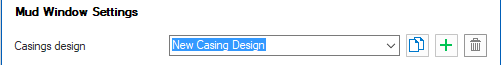
Add new casing design. click to enlarge
You can define the new casing seats by entering the desired casing depths. The application begins drawing the design when you press the Enter key on your keyboard after defining the first casing seat. At the same time, the mud windows are automatically calculated based on the available mud window. You can manually edit the mud window for the entered casing depth by checking the box in the User defined MW window column on the Along Wellbore form.
You can create multiple designs and you can switch between designs. Click (Re)Calculate on the Along Wellbore form to apply the newly selected design. You can also visualize, review and/or edit your casing designs in the Casings tab of the Well Table.
Adding and removing casing seats
For your casing design, you can manually add a new casing seat entry by clicking into the Mud Window table and specifying a casing MD and OD. You can also use the Add Casing Section button to create a new casing seat which will be automatically populated with parameters based on your input data. The new casing seat appears in the Well schematic track.
To remove a casing seat, click in its corresponding row in the Mud Window table and ensure that the row is active (the black arrow indicator ![]() moves to the row), click on the indicator so that the entire row is selected, and then press the Delete key.
moves to the row), click on the indicator so that the entire row is selected, and then press the Delete key.
Graphically moving casing seats
You can also graphically edit a casing seat in the Well View. Activate Edit Casing Scheme tool from Editing Tools, then position the mouse pointer over one of the blue triangles indicating the casing point, then, left click and move the casing point up or down with the mouse. After you reposition the casing point, the mud windows update to reflect the new casing depth. The mud window table is also updated accordingly.